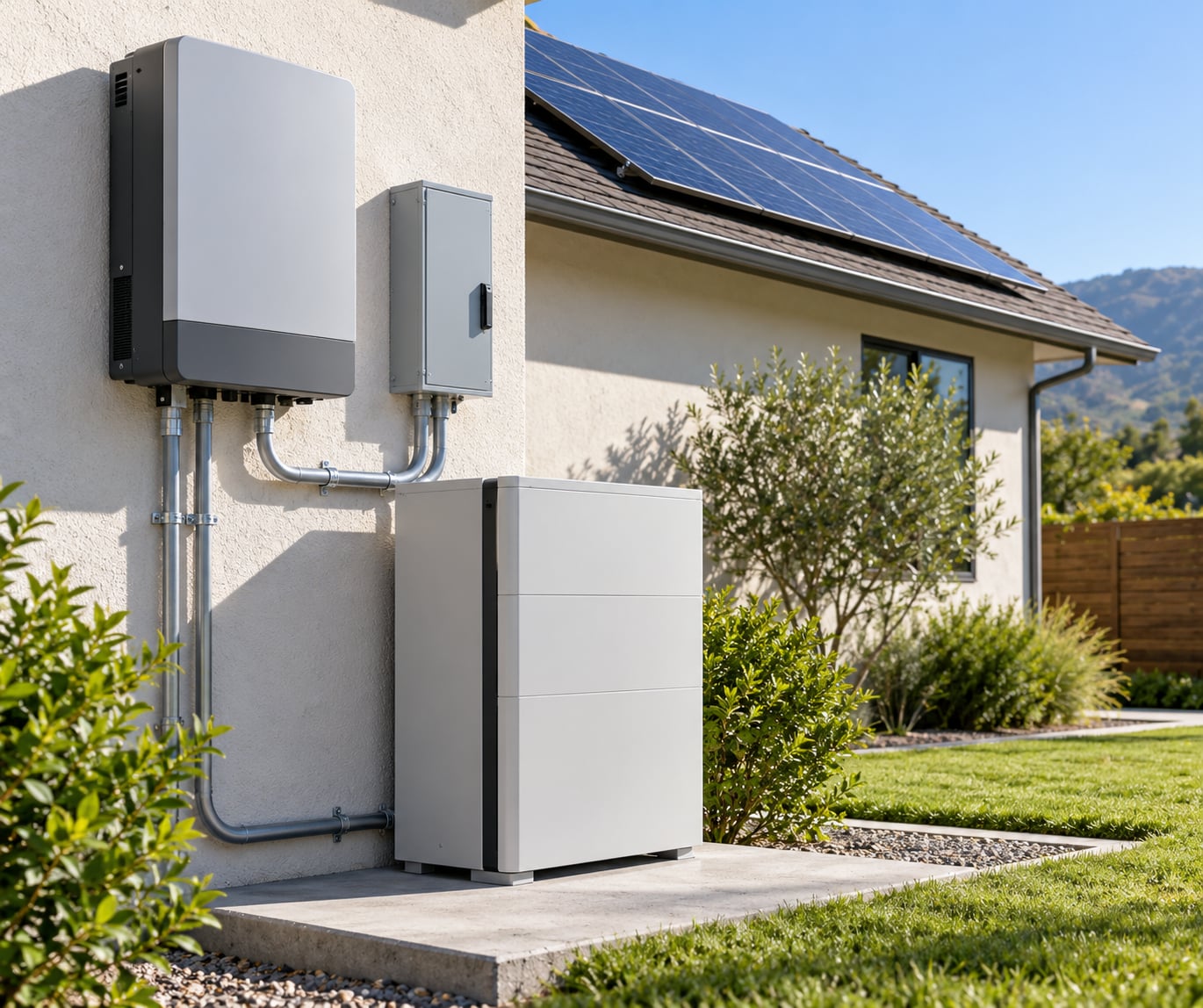
A transfer switch works with solar by physically moving your home’s circuits from one power source to another: it opens the connection to the utility, then closes the connection to a solar inverter, battery bank or portable power station, and it never lets the two sources touch at the same time. On a grid-tied array with no battery, that switch is what makes your panels go quiet the moment the power goes out. Adding a battery-backed or hybrid inverter is what lets solar actually carry loads through an outage.
The switch itself is a simple device. Deciding what solar can power, and whether the hardware will even run without a grid, is a question for the inverter and the battery — not the switch.
Table of Contents
- What Does a Transfer Switch Do With Solar?
- How a Transfer Switch Works With Solar Power
- How a transfer switch works with solar, step by step
- The Parts That Make the Transfer Happen
- Where the battery bank actually connects
- What Happens During Normal Operation and an Outage?
- Solar backup architectures at a glance
- Manual, Automatic, and Transfer-Switch Types
- How Solar Inverters and Transfer Controls Cooperate
- What AC coupling changes
- How to Choose the Right Transfer Switch for Solar
- Safety and Installation Requirements
- Common Problems and Troubleshooting
- How to test a transfer switch after installation
- Frequently Asked Questions
- Do solar panels use a transfer switch?
- Do you have to turn off the main breaker when using a transfer switch?
- Will solar work during a power outage with a transfer switch?
- What are common problems with transfer switches?
- Do I need a transfer switch or a critical loads panel?
- Conclusion
What Does a Transfer Switch Do With Solar?
A transfer switch is a mechanical device with two power sources and one load side. Its only job is to select which source feeds the load and to make sure the sources are never connected together. That last part matters more than people expect.
If a grid connection and a live inverter were bridged at the same time, utility power would flow back into the grid, which is dangerous for lineworkers and prohibited by electrical code. Isolation is not a nicety here — it is the whole reason the device exists.
Solar systems use transfer hardware in three broad arrangements:
- Grid-connected: panels feed a grid-tied inverter, and the utility supplies everything during an outage. A transfer switch may still be present to hold a portable power station or generator as a backup source.
- Inverter-based: a standalone or hybrid inverter forms its own grid, and the transfer switch decides whether that inverter or the utility is feeding your circuits.
- Battery-backed: the switch sits between the utility side and a battery-backed inverter with its own critical loads subpanel, so a defined set of circuits keeps running when the utility drops out.
How a Transfer Switch Works With Solar Power
Here is how a transfer switch works with solar during a normal switching cycle. The manual version uses a handle and a mechanical time delay; the automatic version senses the grid and acts on its own, but the sequence underneath is identical.
How a transfer switch works with solar, step by step
- Watch the primary source. The switch monitors the utility feed for voltage on a continuous basis. On automatic units, a sensing relay looks for the grid reference signal; a manual unit relies on you noticing.
- Detect the loss. When voltage falls out of range, the switch opens the grid connection completely. Manual units can be configured with a time delay so a momentary sag — a motor starting, say — does not trigger a transfer.
- Isolate before connecting. A mechanical interlock makes it physically impossible for both legs to be closed at once. This is break-before-make switching, and it is the core safety behavior.
- Close the backup leg. The inverter or power station output feeds the load side. If that source takes a moment to come up, the gap is where a transfer switch earns its rating — fast-switching units keep the gap short enough that most electronics never notice.
- Serve the load. The selected circuits run from the backup source until the grid returns and the battery or generator has recovered to a set level.
- Return to the grid. Once utility voltage is stable for the programmed delay, the switch opens the backup leg and re-closes the grid leg. Many units also wait for the battery to reach a specified state first, so a short outage does not immediately drain it again.
One user on DIY Solar Forum put it more bluntly than any manufacturer’s manual: the transfer switch just selects which source the input power comes from, and it does not do anything else. Source priority — grid first, or solar first — is a setting, not a law. Some installers deliberately run solar-first so the array covers the load before the utility is called on.
The Parts That Make the Transfer Happen
A solar transfer arrangement is a chain, and it helps to walk it from the roof down:
- Transfer switch or changeover device. The switching element itself, either a lever handle with a spring return or an electrically actuated contactor with a control board.
- Solar inverter or charge controller. Converts the array’s direct current into usable alternating current, and in most cases shapes the output to match household voltage and frequency.
- Service panel. The main distribution board, including the main breaker and, usually, the utility disconnect.
- Battery bank or backup source. The stored energy, and in a hybrid setup the reason the inverter can form its own grid at all.
- Disconnects. Code-required means of isolating each source for service, including the inverter disconnect and, in many jurisdictions, a rapid shutdown device at the array.
- Monitoring equipment. Metering and communications that tell you which source is live and how much energy the battery holds.
Where the battery bank actually connects
On a typical hybrid installation, the battery connects to the hybrid inverter, not directly to the transfer switch. The inverter’s alternating current output is what reaches the switch. Wiring the battery into the switch bypasses the charge management and safety controls the inverter provides, and it is not how these systems are designed to operate.
What Happens During Normal Operation and an Outage?
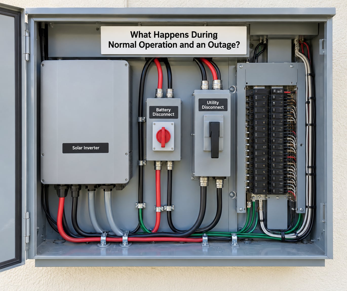
On an ordinary day with the grid up, a grid-tied array feeds the house and any surplus flows out through the meter. Nothing in the transfer switch is doing anything, because there is no reason for it to. It sits there waiting.
When the grid fails, the interesting part starts. A standard grid-tied microinverter or string inverter needs the grid’s reference signal — a steady frequency, normally 60 Hz — to know what a valid waveform looks like. Lose it and the inverter shuts down within a fraction of a second to protect utility workers. The panels are still catching sunlight, but they are producing nothing.
This is the single biggest surprise for people new to solar backup. One DIY Solar Forum user put it directly: you are not going to be able to run your micros directly to the transfer switch and have them work when the grid goes down. A transfer switch cannot fix that, because the problem is upstream of it.
What works is routing grid-tied production into a battery-backed inverter. That arrangement — often called AC coupling — gives the inverter an AC input to draw on and a battery to carry loads when the utility disappears. The same forum’s long-running example does exactly this: a grid-tied microinverter system feeds an off-grid inverter with a large battery bank, and a manual multi-circuit transfer switch feeds the household circuits continuously.
Solar backup architectures at a glance
| Setup | Runs solar in an outage? | What it needs | Main limit |
|---|---|---|---|
| Grid-tied only, no battery | No | Nothing extra | Panels shut down the moment the grid drops |
| Grid-tied with battery backup | Yes, on backup circuits | Battery, hybrid inverter, transfer control | Battery capacity sets runtime |
| Hybrid inverter with battery | Yes, on the loads it is sized for | Battery and a critical loads subpanel | Whole-home loads usually exceed it |
| AC-coupled retrofit | Yes | Existing array plus a battery-backed inverter | Existing microinverters still drop out on their own |
| Off-grid with transfer switch | Yes, always | Standalone inverter, battery, switch | You manage the grid hand-off yourself |
Recovery is the mirror image of the outage. Grid voltage returns, stays stable through the time delay, and the switch re-closes the grid leg. What happens to any excess production on a small backup subpanel depends entirely on the equipment: with a hybrid inverter it charges the battery first and exports the rest; on a small standalone system, surplus is frequently curtailed rather than sent anywhere.
Manual, Automatic, and Transfer-Switch Types
| Feature | Manual transfer switch | Automatic transfer switch |
|---|---|---|
| Who operates it | You, with a lever handle | Control board, on grid sensing |
| Transfer timing | Instantaneous, whenever you throw it | Adjustable time delays, often several seconds |
| Outage awareness | None — you find out the power is out | Detects loss and returns on its own |
| Typical use with solar | Off-grid and semi-off-grid homes, portable power stations | Whole-home backup where nobody is there to switch |
| Known quirk | You can leave a circuit on the wrong source | Budget units can hunt between sources when a battery is low |
The hunting behavior is worth knowing about in advance. Forum users report automatic units that see a low battery, hand back to the grid, then reload and switch again — a cycle you can hear happening in a quiet house. It usually means the source-priority settings and the battery’s state-of-charge thresholds need adjusting, or the battery is simply too small for the load.
A third option sits inside the inverter itself. Many hybrid inverters contain an integrated automatic transfer mechanism, and microinverter systems can offer a battery-backed feature that forms a small local grid. That path can remove the standalone transfer switch from the design entirely, which is worth asking an installer about before you buy a separate box.
How Solar Inverters and Transfer Controls Cooperate
Two different mechanisms get confused constantly, so it is worth separating them cleanly. Anti-islanding is the inverter refusing to run on its own without a grid signal. Transfer control is the hardware deciding which source is connected. One is a safety shutdown triggered inside the inverter; the other is a switching decision made outside it.
What AC coupling changes
In a grid-tied, non-battery system, the microinverters see only one AC reference, the utility, and they follow it. AC coupling routes that grid-tied output into a second, battery-backed inverter instead. The second inverter forms its own grid during an outage, the microinverters now see that reference and keep producing, and the transfer control decides which of those two sources your circuits actually see.
Standalone inverters do something different again. They always form a grid, so they can run a house with or without the utility present, and the transfer switch simply manages which side of the system is energized. That is why off-grid systems can run indefinitely on solar and battery while grid-tied-only systems cannot.
How to Choose the Right Transfer Switch for Solar
Start with the loads, not the equipment. Do a power audit before buying anything — several forum users recommend matching a real budget of essentials rather than sizing a large battery for a single air conditioner. Then work through these criteria:
- Essential loads or the whole home. Essential-load subpanels cost far less to support and let a modest battery carry a meaningful list of circuits.
- Voltage and circuit count. Many residential transfer switches offer only 120 V branches, which makes 240 V loads — a well pump, a clothes dryer, most heating — impossible. Check this before anything else.
- Current rating. The switch must be rated above the largest load it will carry, with headroom for motor starting current.
- Switching method. Manual for a home where someone can reach the switch; automatic for refrigeration, medical equipment or a house that is empty during storms.
- Enclosure and environment. Indoor, outdoor or weatherproof, depending on where it will be mounted.
- Control compatibility. If a battery or portable power station sits on the backup side, its charge controller, output type and pure sine wave output all have to agree with the switch.
- Distance and permits. There is a practical ceiling on how far a portable source can sit from the switch, and installation almost always requires a permit.
One more thing to weigh: where excess production goes. If your backed-up circuits draw less than the array produces, you need to know whether the inverter charges the battery, curtails the surplus, or exports it. Asking that question early avoids surprises later.
Safety and Installation Requirements
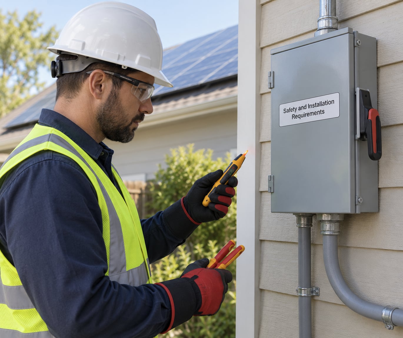
Working on any part of this system means working on service conductors and energized equipment. Panels generate DC voltage whenever they are lit, whether or not the system is switched off. Opening a service panel, sizing disconnects or connecting utility equipment belongs to a licensed electrician, and a permit is normally required.
Ask about the elements that actually reduce risk: lockout and tagging before any work, correct grounding and bonding, overcurrent protection sized to the conductors, and rapid shutdown where the code in your jurisdiction calls for it. Requirements for house batteries tightened under the 2020 National Electrical Code, and local rules vary, so the local authority having jurisdiction is the one to ask.
Follow the manufacturer’s instructions for the inverter, the battery and the switch as three separate pieces of equipment. A transfer switch that is fine on its own may not be approved for use with a specific battery, and that approval is not something to assume.
Common Problems and Troubleshooting
Most transfer switch complaints fall into a handful of recurring patterns:
- No transfer when the grid fails. Usually the backup side cannot start, or the source is not configured as the switch expects. Confirm the battery has charge and the inverter is in the right operating mode.
- Nuisance trips. Time delay settings are too tight for your loads, or a motor-starting surge is tripping the switch. Extending the delay often solves it.
- Wrong source selected. On a manual unit, a handle still sitting in the wrong position. On an automatic unit, a source-priority setting that does not match your intent.
- Battery will not carry loads. Often a state-of-charge threshold set too high, or a battery too small for what you are asking of it. Forum users describe this as the unit switching back to grid the moment the battery dips.
- Inverter communication errors. A monitoring or control link between the inverter, the switch and the battery has dropped out.
How to test a transfer switch after installation
Test with the utility breaker open, using the switch’s own test button if it has one, and confirm which circuits actually lose power and which stay live. A licensed electrician will also verify the switching sequence and the time delays under real conditions. Do not test by unplugging a live source yourself.
Frequently Asked Questions
Do solar panels use a transfer switch?
The panels themselves do not. A transfer switch sits downstream of the inverter and decides whether your circuits are fed by the utility or by a solar source. Most grid-tied systems do not need one, because the inverter is designed to follow the grid. You need transfer hardware when you want a second source, such as a battery-backed inverter, a portable power station or a generator.
Do you have to turn off the main breaker when using a transfer switch?
No. A transfer switch is built to isolate the sources, which is the entire point of the device, so the main breaker normally stays on and ordinary circuits keep running. Several users on DIY Solar Forum confirmed this directly, and it is where a lot of confusion sits, because people often assume they also need a separate critical loads panel. You do not, though a subpanel is still the cleaner way to define which circuits get backed up.
Will solar work during a power outage with a transfer switch?
Not by itself. Standard grid-tied microinverters and string inverters need the grid’s reference signal, normally a steady 60 Hz, and they shut down within a second of losing it to protect utility lineworkers. A transfer switch cannot change that. To run on solar during an outage you need a battery-backed or hybrid inverter, and often an AC-coupled path that lets the grid-tied array keep producing.
What are common problems with transfer switches?
The recurring ones are failure to transfer at all, nuisance trips from time delays set too tight, the wrong source being selected, a battery that will not hold loads, and inverter communication errors. Budget automatic units also hunt between sources when the battery runs low. Start with the monitoring equipment and the operating mode, then have a licensed electrician diagnose anything involving the panel or the disconnects.
Do I need a transfer switch or a critical loads panel?
They solve different problems. The critical loads panel defines which circuits get backup power; the transfer switch decides which source feeds them. Many homeowners use both, because the subpanel keeps the backed-up circuits organized and the switch handles the source change. A transfer switch with its own circuit list can cover a smaller system on its own, which is common with portable power stations.
Conclusion
Understanding how a transfer switch works with solar comes down to two separate things. The switch picks the source, safely and never both at once; the inverter, the battery and the safety controls decide what solar can actually power once the switch has made its choice. Grid-tied panels without a battery produce nothing in an outage, and no switch changes that.
Start by listing the circuits you would miss most, size the system around that list, and then have a licensed electrician design the transfer arrangement and pull the permit.