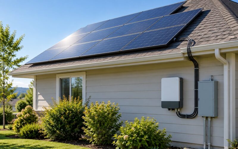
Grounding works by giving fault current a low-impedance path to earth, so a breaker or fuse disconnects the problem instead of energizing metal someone can touch. In a solar system, the frames, racking, inverter and battery enclosures are bonded together and tied to the building’s grounding electrode system. Nothing is “drained” into the soil, and grounding has no effect on how much power your panels produce.
That last point clears up the most common misconception. Solar modules are a floating direct-current source: their positive and negative conductors are not connected to earth, and current does not leak away into the ground. What gets grounded is the exposed metalwork around them, so that if insulation fails or a wire gets damaged, current has somewhere safe to go.
Table of Contents
- How Grounding Works in Solar Systems
- What Is Grounding in a Solar Power System?
- Safety grounding
- Functional grounding
- Surge and lightning protection
- The battery ground
- What Does the Grounding Electrode Do?
- Which Solar System Parts Need Grounding?
- Why a clamp alone is not enough
- Bonding and grounding are different jobs
- Transformerless inverters and the one-bond rule
- What Happens When a Solar System Has a Fault?
- How Does Grounding Differ in Grid-Tied and Off-Grid Systems?
- Grid-tied systems
- Off-grid systems with batteries
- Separate structures and multiple arrays
- Do Lightning Protection and Grounding Do the Same Job?
- How Is Solar Grounding Installed and Checked?
- How a compliant install goes together
- What gets checked afterward
- Common mistakes worth watching for
- Frequently Asked Questions
- Do solar panels need to be grounded?
- Is grounding the same as connecting a solar panel to Earth?
- Will grounding protect my solar system from lightning?
- Do solar batteries need a grounding conductor?
- What happens if you don’t ground a solar array?
- Does grounding make solar panels produce more power?
- Conclusion: What to Do First
How Grounding Works in Solar Systems
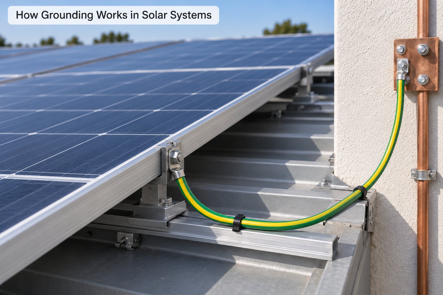
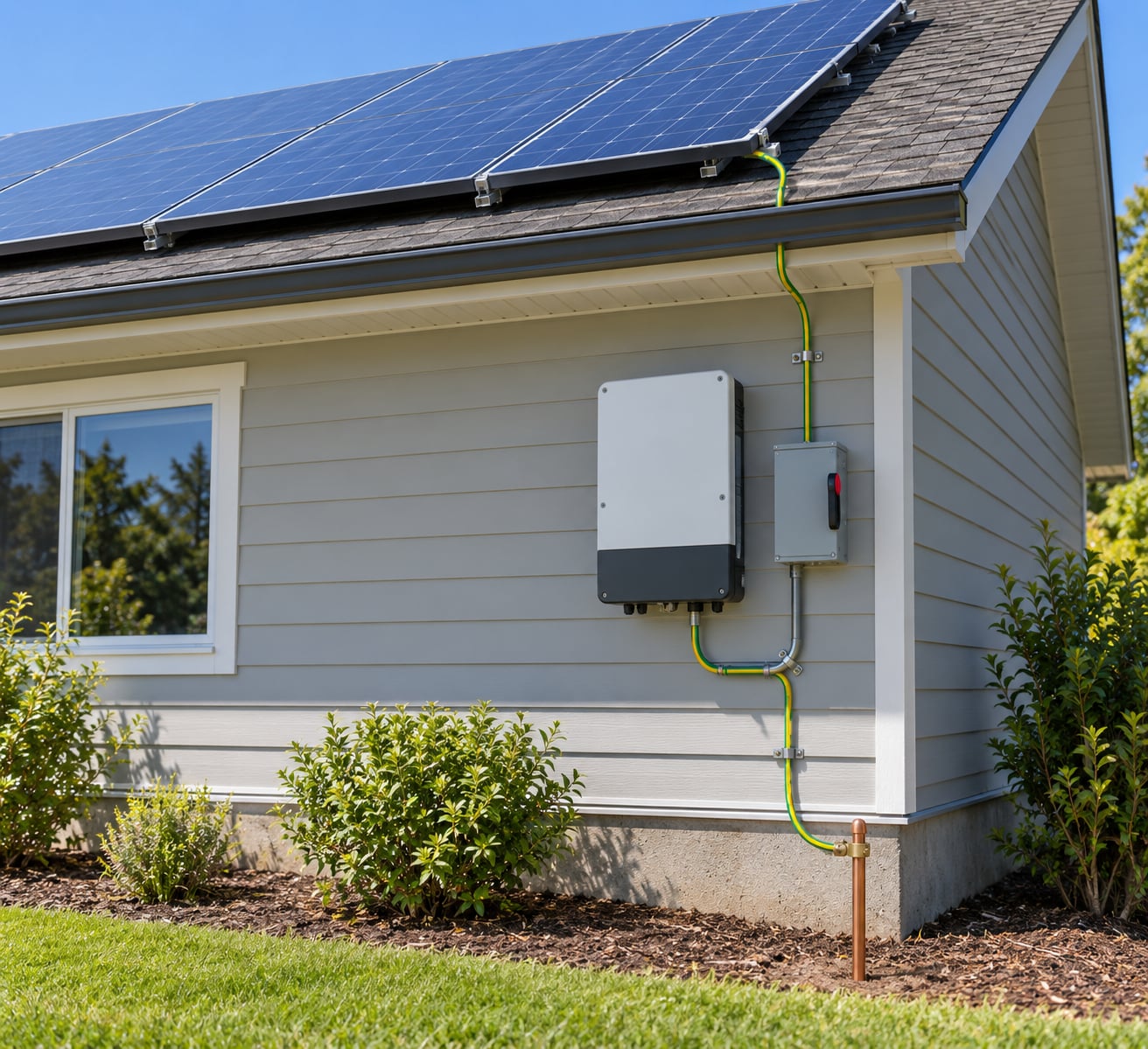
Grounding works by connecting exposed metal parts to earth with a conductor that has very low impedance, giving any fault current a path that trips the protective device within milliseconds. That path runs from the module frame through the equipment grounding conductor, into the inverter, and out to the grounding electrode system. Its job is safety, not performance.
Grounding and earthing are the same thing under two names. US electricians and the NEC say grounding; UK and much of the rest of the world say earthing. Both describe the connection between a system and earth.
Three terms get mixed up constantly, so it is worth sorting them out before anything else.
What Is Grounding in a Solar Power System?
Grounding in a solar power system is the deliberate connection of metal equipment to earth so that fault current has a defined route. Two other things get called grounding, and neither is the same thing.
Safety grounding
This is the one that matters for shock and fire. The frames, rails, inverter enclosures, disconnects, combiner boxes and battery cabinets are all electrically connected together, and that network connects back to the building’s grounding electrode system. The protective devices downstream watch for current imbalance, and a fault that touches this network becomes an event they can see and clear.
Functional grounding
Sometimes equipment is earthed for its own reasons, not for fault safety. A satellite dish, a communications antenna or a long run of signal cable may need an earth connection to control noise and signal interference. That is a separate decision with separate requirements, and it does not count as your PV safety ground.
Surge and lightning protection
Grounding and surge protection work together but are not interchangeable. A surge protective device diverts a transient; the grounding system gives that device somewhere to send the energy. More on that below.
The battery ground
Off-grid discussions often mention a “battery ground,” and it confuses people badly. What usually exists is a bonding point on the battery enclosure, tied into the same equipment grounding network as everything else. A battery case is not a return path for the battery’s own energy, and there is no conductor that drains stored charge into soil.
What Does the Grounding Electrode Do?
The grounding electrode is the part of the system that actually touches earth, and its job is to make that connection low enough in impedance that a fault produces enough current to trip protection quickly.
A practical grounding electrode system is rarely a single rod. It can be a rod driven near the building, a concrete-encased electrode such as a Ufer, a ground ring around a structure, the building’s structural steel, or some combination. Your local electrical code decides which ones count, and it may require more than one.
Reusing the home’s existing ground is normal and usually correct. A solar inverter sits on your existing grounding electrode system; it rarely gets its own private rod unless the existing system is inadequate or the array stands far from the building. Installers commonly bond to building steel or a metal water pipe where the code allows it, and to a rod or Ufer where it does not.
Soil matters more than most people expect. Dry, rocky ground reads high on a resistance measurement; damp, conductive soil reads low. A single shallow rod in poor soil can disappoint, which is why several electrodes joined together are often the practical answer.
| Term | What it is | Job |
|---|---|---|
| Equipment grounding conductor (EGC) | Insulated or bare wire running with the PV circuits | Carries fault current from exposed metal back to the inverter or service |
| Grounding electrode conductor (GEC) | Wire from the inverter or service to the electrode | Ties the system to earth |
| Grounding electrode system | Rods, Ufer, ring, structural steel and connections | The actual connection to earth |
| Grounding electrode | A single rod, plate or Ufer | One part of the electrode system |
Which Solar System Parts Need Grounding?
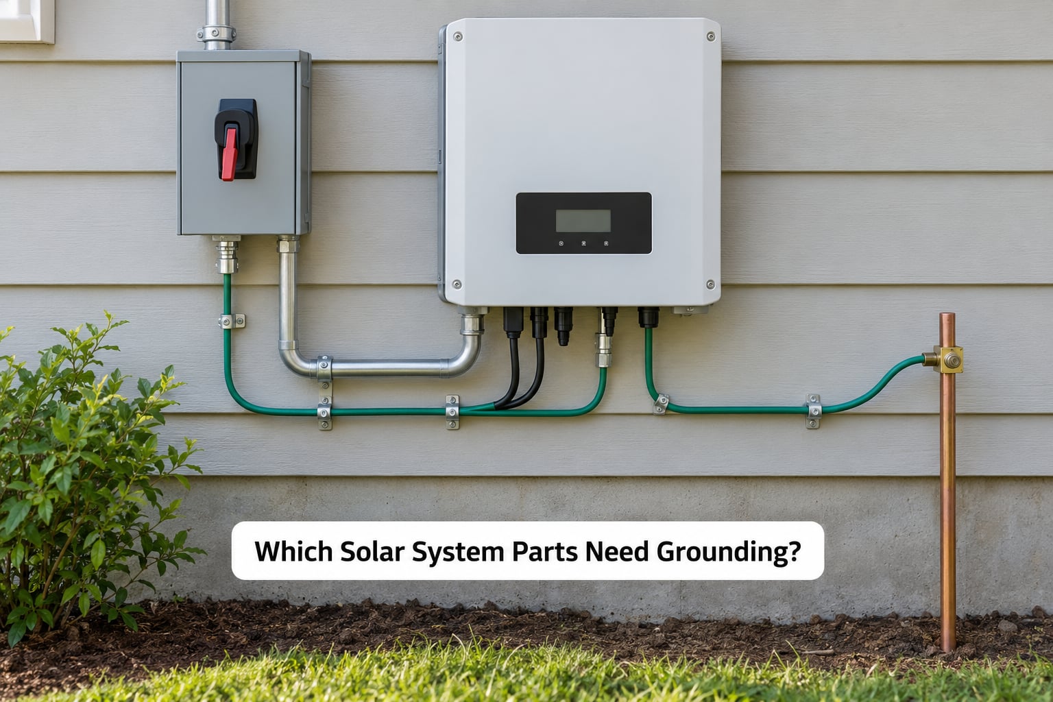
Any exposed metal that a person could touch during a fault generally needs to be bonded: module frames, mounting rails, racking components, inverter housings, the AC and DC disconnects, combiner boxes, monitoring equipment enclosures, conduit, and battery cabinets. The manufacturer’s installation manual and the local code both apply, and where they disagree, the installer follows the more protective requirement.
Why a clamp alone is not enough
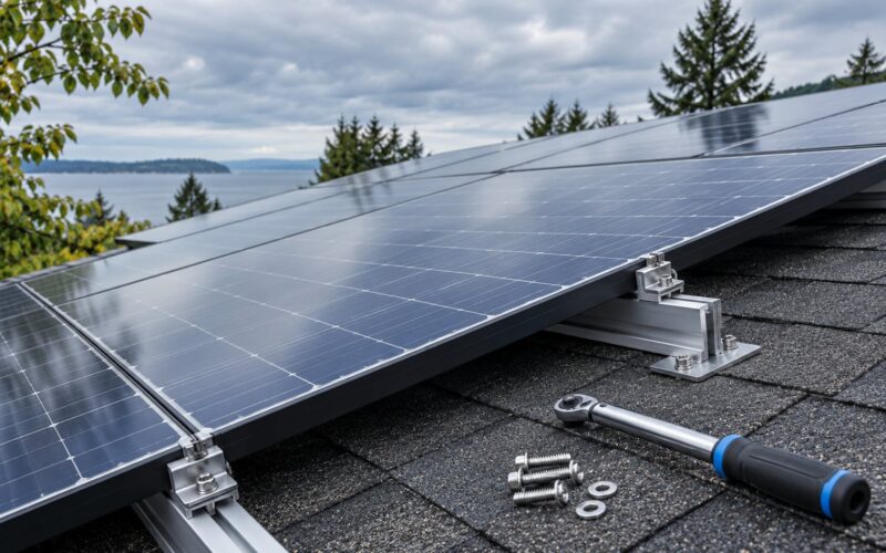
This one detail causes more trouble than any other in DIY discussions. Anodized aluminum has an oxide surface layer, and a clamp that merely sits on a frame can make a mechanical connection without a reliable electrical one. Two solutions are standard: a grounding washer or conductive tab placed under the mid or end clamp so the hardware bites through the oxide into conductive metal, or a dedicated grounding lug with a self-tapping screw driven into a designated frame hole. Installers confirm which of these the module manufacturer allows before anything goes on the roof.
Bonding and grounding are different jobs
Bonding makes two conductive parts electrically continuous so they sit at the same potential. Grounding connects that bonded network to earth. Bonding every frame to its neighbor keeps the whole array at one potential; grounding gives that shared potential a defined reference and a safe place for fault current to go.
| Term | What it connects | Purpose |
|---|---|---|
| Grounding | The equipment network to earth | Safety path for fault current |
| Bonding | Frames, rails and enclosures to each other | One equal potential across all exposed metal |
| Neutral-ground bond | The inverter’s neutral to its ground terminal | Gives the inverter a voltage reference and enables fault detection |
Transformerless inverters and the one-bond rule
Most modern inverters and microinverters have no isolation transformer, so they need a neutral-to-ground bond to have a reference and to see imbalance. That bond belongs in one place on the system, per the manufacturer’s instructions. A second bond in the middle of the run creates parallel neutral paths, which is exactly what anti-islanding and fault detection are designed to avoid.
What Happens When a Solar System Has a Fault?
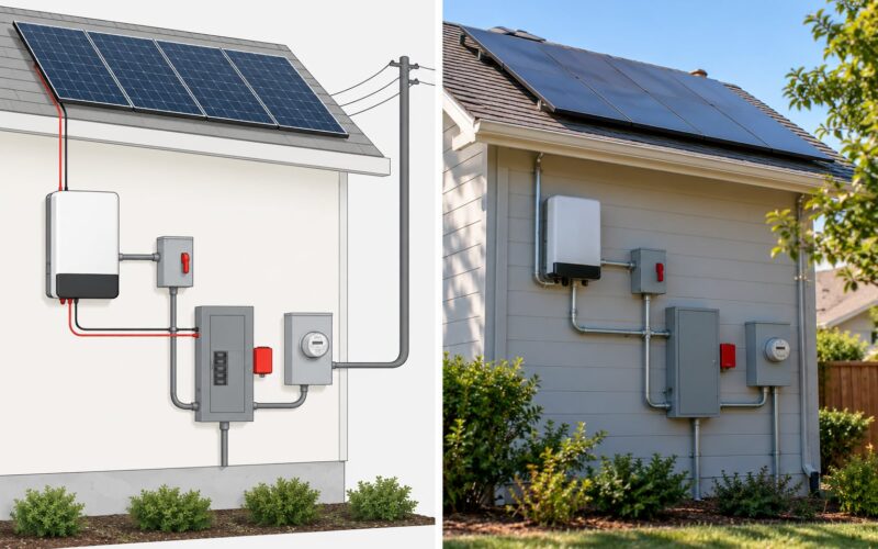
A fault is any unintended connection between an energized conductor and grounded metal. A damaged cable whose insulation rubs through, a conduit fitting that cuts a wire, water getting into a junction box, or a failed internal component can all cause one. Here is the path that fault current takes, and why the breaker clears it.
- Current leaves the conductor at the fault point. The insulation fails and the live conductor touches a grounded frame, enclosure or fitting.
- It enters the metalwork through a bond. The frame, rail or enclosure carries it along the bonded network toward the array’s grounding point.
- It enters the equipment grounding conductor. The EGC runs alongside the PV wiring back to the inverter, which means the fault current does not have to travel through the house wiring to find a way out.
- It passes through the inverter’s ground bus bar. The imbalance between the current flowing out and returning is what the inverter’s ground fault detection registers.
- It continues down the grounding electrode conductor. This is the low-impedance segment that makes the whole path work, since the electrode and soil at the far end finish the circuit.
- Protective devices act. The inverter’s ground fault protection shuts the system down, and a breaker or fuse further upstream opens if the fault is severe enough. Because the path has low impedance, the current is large enough to clear fast.
That last step is the entire point. If the path is long, thin or corroded, the impedance rises and the fault current stays too small to trip anything. Now the frame sits at an elevated voltage and the protection never sees the event. Grounding is not decorative; it is what makes protection measurable.
On grid-tied systems the ground fault relay also serves anti-islanding, so a system that cannot see ground faults is a system that cannot shut down correctly when the grid dies. On off-grid systems with batteries, the same fault is more dangerous because the supply keeps running after the fault. There is no grid to disconnect it, and the battery bank holds enough energy to sustain the fault indefinitely until something opens the circuit.
How Does Grounding Differ in Grid-Tied and Off-Grid Systems?
The safety principle is identical in both. What changes is where the reference comes from and how much energy is available to keep a fault burning.
Grid-tied systems
The utility provides a grounded neutral at the service, and the PV system bonds to that existing grounding electrode system. Inverters have disconnecting means, and the ground fault relay coordinates with the service breaker. A fault trips the inverter first and the breaker only if needed.
Off-grid systems with batteries
There is no utility reference, so the system establishes its own. Batteries often have a bonding point on the case, and the inverter’s ground fault protection does the heavy lifting, since it is the only thing watching. The battery bank changes the risk profile completely: energy is stored on site and will not stop feeding a fault until a device opens. That is why code and manufacturer requirements around battery enclosures, disconnects and grounding are strict, and why an off-grid system should never be commissioned without a qualified installer testing it.
Separate structures and multiple arrays
An array on a detached garage, a carport or a ground mount is a separate structure, and the question of how it connects back comes up constantly. The practical consensus among installers is to run the equipment grounding conductor back to the existing grounding system and avoid creating additional electrode paths between buildings, which can introduce unintended potential differences between them. Bonding every frame at each array, and keeping a single defined reference, is the approach most discussed on solar DIY forums.
Do Lightning Protection and Grounding Do the Same Job?
No. They are related, and they work together, but they solve different problems.
Grounding provides a permanent low-impedance path so ordinary fault current can be detected and cleared. Surge protection handles fast, high-voltage transients from lightning or switching events. Lightning protection is a third layer, typically rods and down conductors on the structure itself, designed to intercept a strike before it enters the building.
Surge protective devices only work well when the connection to the grounding point is short and straight. Every extra foot of conductor adds impedance, and surge energy has microseconds to escape. A device with a long, meandering ground lead performs poorly no matter how good the device is, which is why installers specify placement near the conductors being protected.
Grounding your array does not stop a lightning surge from damaging equipment. It makes the system safer during faults and gives a surge device a place to send what it diverts.
How Is Solar Grounding Installed and Checked?
This is high-voltage direct-current work on equipment that stays energized whenever the sun is up. I am describing the sequence so you can recognize a correct installation and talk to your installer intelligently, not so you can build one. All bonding, electrode and inspection work belongs to a licensed electrician or a qualified solar installer working to the manufacturer’s instructions and local code.
How a compliant install goes together
Each module frame is bonded with the approved hardware, a grounding washer under the clamp or a lug and self-tapping screw in a designated frame hole. Frames are bonded to rails, rails to racking, and the array is bonded to the equipment grounding conductor.
The EGC runs with the PV circuit conductors back to the inverter or to the appropriate disconnect, where it lands on the inverter’s ground bus bar. A grounding electrode conductor ties that point to the building’s grounding electrode system, using the existing rod, Ufer, ground ring or structural steel the code accepts. Transformerless inverters get their single neutral-ground bond where the manufacturer specifies it.
Grounding is not a performance setting, so nothing on the inverter menu changes the outcome. It is fixed hardware.
What gets checked afterward
Continuity testing confirms a real low-resistance path from each frame through the EGC to the grounding point, and catches the missed bond that a visual inspection misses. Polarity checks confirm the current-carrying conductors are correct. Insulation resistance testing on the PV circuits verifies the cabling itself. Ground resistance measurement at the electrode checks the earth connection against what the local code requires.
That last measurement is the one most homeowners never see and most find interesting when they do. It tells you whether the electrode is genuinely low impedance in your soil, which is not a given on rocky or dry ground.
Common mistakes worth watching for
Grounding each frame separately with a thin wire back to a distant point instead of bonding frames to each other. Relying on a clamp sitting on an anodized frame with no approved piercing hardware. Using the neutral as a ground. Creating a second neutral-ground bond in a transformerless system. Adding a new electrode between two buildings that already share a reference. And skipping the electrode upgrade when the existing system reads high.
Metal roofs add their own wrinkle. The roof structure may be usable as a bonding point, but only if the roofing material and the attachment method allow it, and only where the code and the module manufacturer permit it. Sealing penetrations correctly while meeting that requirement is a judgement call for the installer, which is why metal roof grounding comes up so often and gets answered so thinly.
Portable and folding panels are a separate case again. Typically the panels and their leads are double insulated with no exposed metal requiring bonding, and the portable power station provides the reference. When in doubt, the unit’s manual and the manual for the station decide, and the answer is not always the same across models.
Frequently Asked Questions
Do solar panels need to be grounded?
The panels’ positive and negative conductors are not earthed, because modules are a floating DC source. What generally requires grounding or bonding is the exposed metalwork: module frames, mounting rails, inverter and disconnect enclosures, combiner boxes, conduits and battery cabinets. Manufacturer instructions and local code decide exactly which parts need it and how each connection must be made.
Is grounding the same as connecting a solar panel to Earth?
Not exactly. A module’s positive and negative conductors are part of the electrical circuit and float relative to earth. The equipment grounding conductor is a separate wire that connects exposed metal parts to the building’s grounding electrode system, and it carries current only during a fault. Nothing drains operating power into the soil.
Will grounding protect my solar system from lightning?
Grounding supports electrical safety, but it does not by itself stop a lightning surge from damaging equipment. A properly installed surge protective device, correctly sized conductors, a short connection to the grounding point, and lightning protection on the structure are what handle a strike. Grounding gives that equipment a defined path to work with.
Do solar batteries need a grounding conductor?
The answer depends on the battery chemistry, manufacturer design, inverter configuration and local code. Some systems include a bonding point on the battery enclosure that ties into the same equipment grounding network as the rest of the system, while others use a different arrangement. Off-grid systems deserve particular care because stored energy keeps feeding a fault until a device opens the circuit.
What happens if you don’t ground a solar array?
Four things follow. Exposed metal can become energized during a fault, creating shock and fire risk through touch and step voltage. Surge and lightning events have no low-impedance path, so equipment is far more likely to be destroyed. The installation fails inspection and permitting, which can hold up a sale or a claim. And you carry liability for damage that a compliant system would have prevented.
Does grounding make solar panels produce more power?
No. Grounding is a safety function with no effect on output, and there is no setting on an inverter that changes it. Adding a ground rod or extra bonding will not raise production, improve efficiency or extend panel life. Grounded and ungrounded arrays generate the same power under the same conditions; the difference is what happens when something fails.
Conclusion: What to Do First
Ask the installer to show you the equipment grounding path on the system plans and confirm it against the manufacturer’s instructions and your local code: how each frame is bonded, where the equipment grounding conductor terminates, which neutral-ground bond exists, and what the grounding electrode system consists of. If you want independent proof, hire a qualified electrician to measure ground resistance and verify continuity. That is the one step that settles every other question about how grounding works in solar systems.